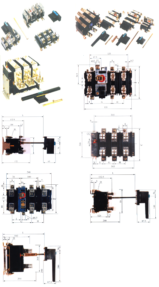
1. Fully closed structure
QSA series switch full closed structure ensures stable performance and improvement of work reliability.Both moving and static contacts,which cannot be seen exteriorly,are mounted ina pressed housing made of new type electric enguneeing plastice.There are connecting terminals.fuse boby socket(QSA) or visible copper conductor QA of series connection and QP of parallel connection,operation axle sleeve,and auxiliary contact socket,etc.mounted outside the housing.Dismantle or assembly is not allowed without permission for strict technique control for assembly.
2.Unique contact system
QSA series switch owns a unique contact system of rolling instert type,composed of two sets of double-breapoint each phase.In structure,rollers of different length and diameter andf quantity will compose different contact system and two sets of contacts in series or parallel connection will meet the circuit of different electrical amperage and work categories. Applying this contact system,the current will pass through four rollers and greatly reduce the electric requlsion when the contact closes.(theoretically,current is1/4,requlsion is 1/6). When the switch is in the state of closing and meanwhile large short-circuit is passing through(under the limit condition,the current may be larger than 100KA),the roller will clamp the stantic contact tinghter as per the reversal parallel law. During the movement,the touching between roller and static contacts belongs to rolling and side firction so as effectively aviod the occurrence of fusion welding.
3.Indepent manpower operation
The operation mechanism of QA series switch is desingned with energy-stirage spring.In spite of switch-on\off is operated with force manually,the moving speed of moving contact is independent of operational force and operation speed,ensuring stable switching performace.
4.Advanced actuator
The actuator is a composed of device transmitting the operation torque to the operation mechanism axle sleeve of switch,and the handle is the part for operator to hold.
①The actuator is composed of handle mounted on the panel and the drving shaft joggled with handle.The extension shaft and the couple can only be used when the driving shaft is not long enough.In fact,it shall take consideration of inbuilt installation of switch in the complete equipment and never mind of inaptitude between the depth of switchgear and handle mounted on the panel.
②The handle is mounted on the panel
③The handle mechanism shall be in conformity with the requirement that the door cannot open when the switch is closed,the switch shall be in breaking position if you want to open the door,the switch cannot be closed if the door is unclosed.
④The handle has a padlock puling buckle.Lock the handle with the padlock. After being pulled out.The handle cannot turn while in breaking or closing position to avoid error operation of non-operator.
⑤The driving couple shall keep 5mm free distance to the surface in parallel with the handle mounting plane so as to avoid affecting normal work.Therefore it is ease in installation and adjistment,and that will not cause any difficulty in operation due to imprecise adjustment.
5.Independent auxiliary contact
The switch may be attached with one or two auxiliary contact boxes.Each auxiliary contact box has pair of NO and a pair od NC contacts.Auxiliary contact box is insert type assembly.It is unnecessary to use screw and is easy to diamantle and assemble. The breaking and making of both auxiliary contact and switch are synchronus.Working principle of QSA series switch:switchingin while rotating the operation handle clockwise;switching off while anticlockwise.